INSTALLING VORTEX GENERATORS ON A GLASTAR
Table of Contents
The first time I first saw Maple in her southern-Michigan hangar that day in September 2018, I noticed that the GlaStar's four delta-wings had not been installed on the wings; Denny Lawrence, the builder, had left them assembled, but unpainted, in a box. Days later as I headed westward in my new plane, I figured the 36-hour trip home to the Pacific Northwest was long enough to learn how she'd handle without them. But by Colorado Springs I knew: she didn't need the delta-wings, she needed micro-vortex generators. See Why VGs? for general information about vortex generators.
Original GlaStar delta-wing vortex generators (uninstalled)
Denny Lawrence assembled the delta-wing VGs, but left them unpainted and uninstalled.
Scope of Project
To understand the scope of installation of VGs, I divided the project into the following phases, which have now been completed:
Phase 1: Record speeds in various flight configurations (no VGs) | Attach tufts to left wing
Phase 2: Fly with tufts installed | Record video | Analyze video and data
Phase 3: Install temporary VGs | Analyze video and data | Relocate VG positions | Retest as necessary
Phase 4: Analyze video and data | Set final location of VGs
As of March 2023 the following phases have not yet been completed:
Phase 5: Remove VGs | Prepare for painting
Phase 6: Paint VGs
Phase 7: Weigh and permanently install VGs
Phase 8: Flight test | Prepare Instructions for Continued Airworthiness | Update Weight and Balance/other documentation
* * * * *
Once home I started looking around for guidance, but there was nothing I could find applicable for GlaStars…until I found Jerry Lundgren of Pacific Northwest Aero in Bend, Oregon (Lundgren, 2020), maker of micro vortex generator kits for experimental aircraft—including GlaStars. My subsequent trip to Bend revealed the path to VG enlightenment: wool-tuft tests!
The key point—why wool-tuft testing is so important to the installation of VGs—is that tufts pinpoint where on the wing the airflow separates from the boundary layer at high angles of attack. With that information, vortex generators can be attached to the wings to control boundary-layer separation.
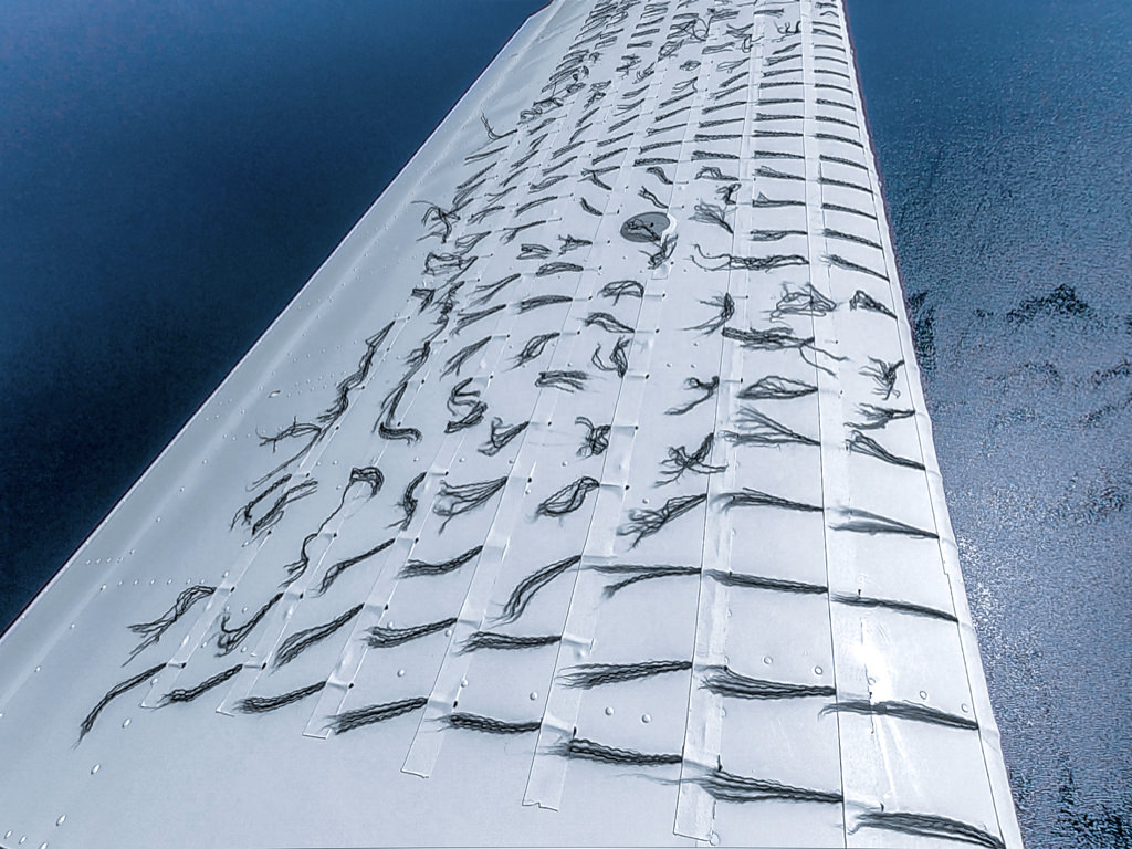
Boundary-layer separation at high AoA (no VGs)
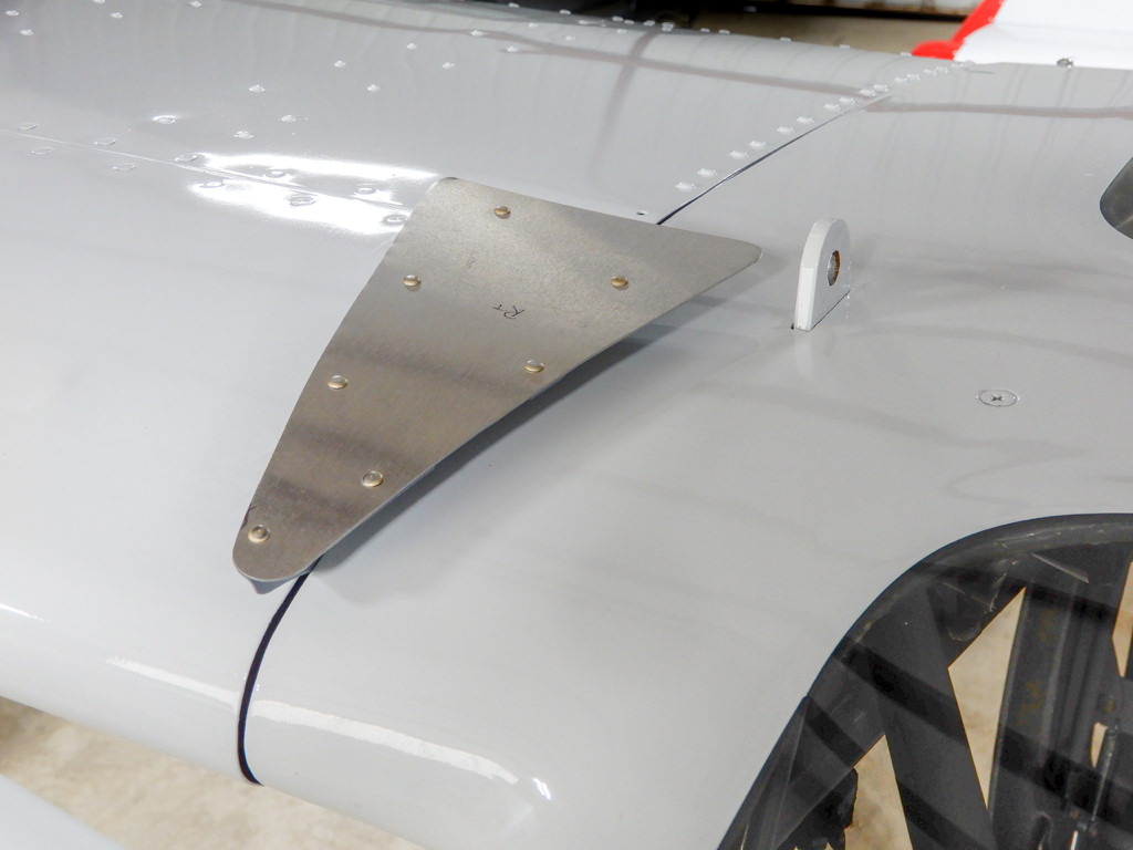
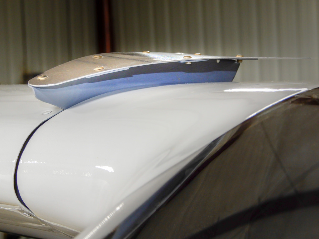
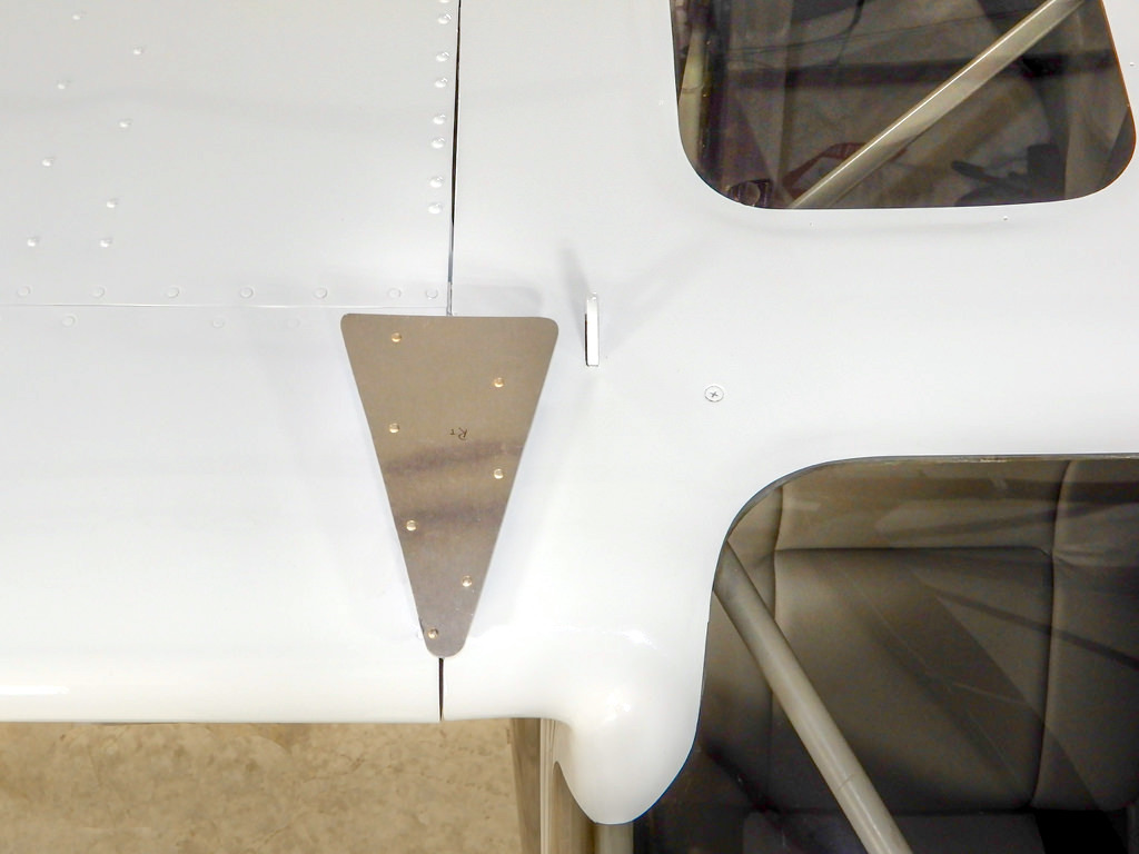
A challenge yet to be faced was lack of a camera platform suitable for recording video of the tufts on the top surface of the GlaStar's wing. I was on my own for that one; I'd never seen camera mounts for high-wing aircraft. Luckily there are two small 'dog-ears' poking through the roof of the cabin (attached to the cage inside all GlaStars and Sportsman aircraft), so I created a design based on that feature.
The camera of choice for this project, the GoPro Hero 7, when mounted on the yet-to-be-constructed 'camera bridge' a few feet above the GlaStar's wing-root looking down and outboard toward the wingtip, would not be able to see movement of tufts past half the wingspan, on account of the camera's wide-angle lens. Therefore, two GoPro camera platforms were needed:
- the 'camera bridge' for the GoPro looking outward from the wing-root toward the wingtip, and
- a 'camera loop' attached to the wingtip's leading edge looking inward to capture a view of tufts attached to the outboard half of the wing.
Creation of these platforms (in advance of the VGs project) were separate projects in their own right; see camera mounts for details.
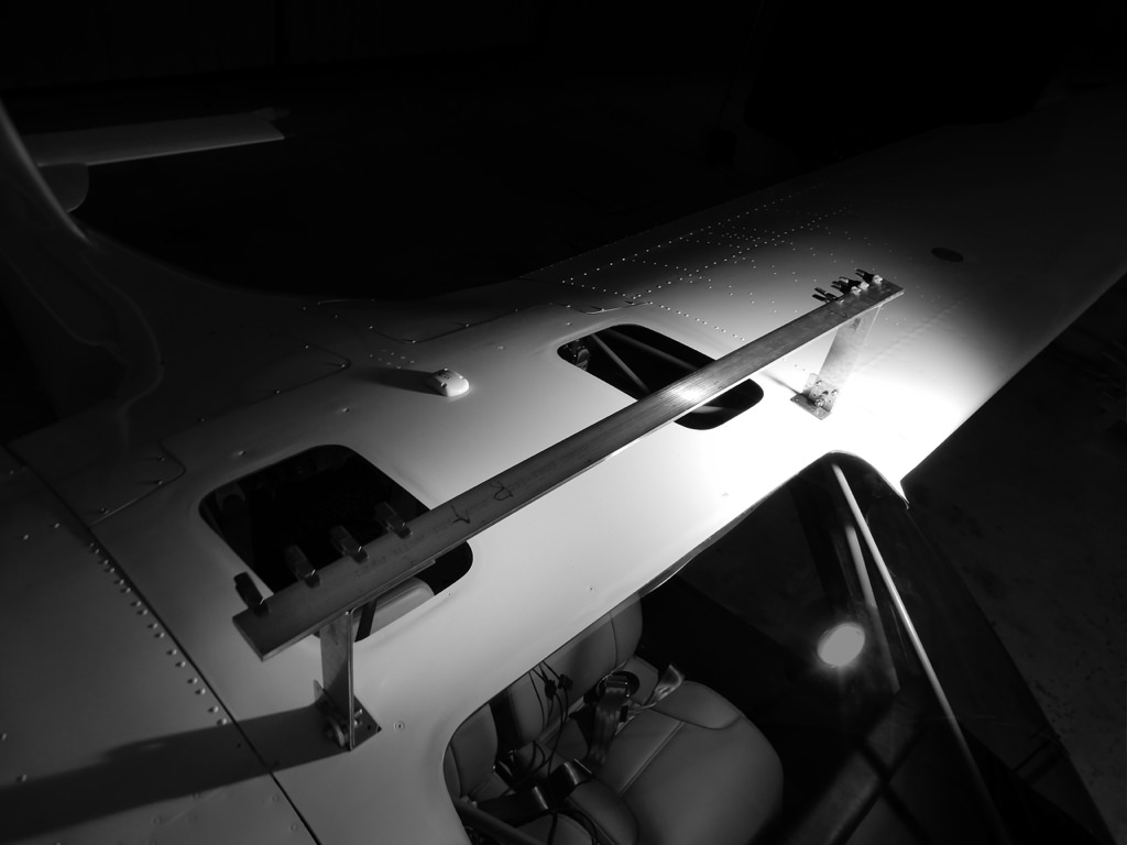
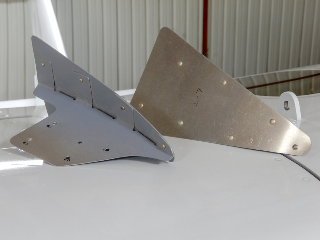
'Camera Bridge' under construction
Jerry pointed out that various lengths, quantities, and placements of tufts can be attached to the wing. I wanted more tufts on the wing for greater detail of the movement of air visible to the camera. Thus, I chose to lay the tufts (which were actually made of acrylic, not wool) every three inches span-wise and cord-wise for a data-rich field of view for the cameras.
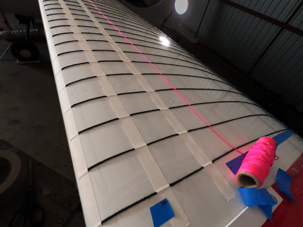
Installing tufts at 3-in square intervals
PHASE 1: Record speeds in various flight configurations (no VGs) | Attach tufts to left wing
Goals:
* to establish a baseline for comparison
* to enable wind-flow analyses
First I flew Maple, with no tufts and no VGs, to establish a baseline showing airspeeds.
STALL-SPEED TEST RESULTS OVER MULTIPLE ATTEMPTS (no tufts, no VGS, wings level)
June 18, 2020
OAT: 16°, 4,000 ft AGL, max gross weight, full aft CG
| configuration | knots | average (knots) |
| * power off, no flaps: | 55; 55, 53, 54, 54, 55 | 54 |
| * power off, half flaps: | 47, 43, 46, 50, 47, 43 | 46 |
| * power off, full flaps: | 40, 40, 40, 41, 41, 40 | 40 |
| configuration | knots | average (knots) |
| power on (1720 rpm) | ||
| * power on, no flaps: | 54, 53, 52, 53 | 53 |
| power on (1660 rpm) | ||
| * power on, half flaps: | 44, 44, 43, 45, 44, 44 | 44 |
| power on (1500 rpm) | ||
| * power on, full flaps: | 40, 38, 39, 41, 41 | 40 |
| configuration | knots | average (knots) |
| top speed (2500 rpm) | ||
| * straight & level | 124, 125, 125, 123, 124 | 124 |
PHASE 2: Fly with tufts installed | Record video | Analyze video and data
Goal: Discover where on the wing the boundary layer separates in various flight configurations
As previously discussed, the goal of the tuft test was to learn where the trouble spots are located on the wing, for subsequent placement of the VGs.
I installed tufts on the left wing in accordance with Jerry's VG installation instructions, then flight tested and recorded the movement of the tufts in the same flight configurations as used in Phase 1. Later, after flying multiple times with the tufts and viewing the video, I realized that while the wing stalls at different airspeeds in different configurations, airflow separation from the wing occurs in the same multiple locations regardless of configuration: power off, power on stalls, with and without flaps, slips, etc. All videos pointed to two major areas where the airflow separated from the wing at the slowest airspeeds and in stalls, in different configurations:
- an area spreading in a V-shape starting just aft of the leading edge near the strut, spreading quickly toward the wing root, trailing edge, and the flap-aileron junction
- subsequently, a second area spreading from near the wing root, then spreading back toward the trailing edge then outward
In slow flight leading to a stall, boundary-layer separation should ideally start inboard at the wing root, leaving the outer parts of the wing at the ailerons to continue producing lift, unstalled, while providing lateral control as the wing approaches its critical angle of attack (Lögdberg, O. (2006), Lin, J. C. (2002), Busch, M. (n.d.)).
However, video and photos showed that boundary-layer separation was actually beginning almost halfway down the span of the wing—not at the wing root. This was the first trouble spot to be addressed.
[video] Flight characteristics before installation of vortex generators
STALL-SPEED TEST RESULTS OVER MULTIPLE ATTEMPTS (with two cameras and tufts; no VGS)
July 10, 2020
OAT: 18°, 4,000 ft AGL, max gross weight, full aft CG
Stall speeds in power off and power on in all configurations with cameras and tufts were about the same as without. See Phase 1 Stall-Speed Test Results (supra).
PHASE 3: Install temporary VGs | Analyze video and data | Relocate VG positions | Retest
Goal: To find VG locations that provide maximum benefit
Jerry's vortex-generator installation instructions called for placing the first pair of VGs about seven percent of wing-chord (aft of the wing's leading edge) and eight to ten inches outboard of the wing root, and space subsequent VG-pairs at eight to ten-inch intervals on centre till reaching the flap-aileron junction, then reduce their spacing to six to eight inch intervals on centre for the remainder to the wingtip. However, after placing the VGs at seven percent aft and with the recommended spacing, post flight-test results were disappointing, both in terms of reduction of stall speed and elimination of the initial boundary-layer separation from halfway down the span of the wing.
This prompted a telephone call to Jerry for consultation. After some discussion, I asked Jerry, "why are the pairs of VGs so far apart? I see other aircraft with much closer spacing of VG pairs, perhaps four to six inches on centre." His answer was that spacing the VGs at eight inches to the flap-aileron junction, then six inches to the wingtip was to avoid drag. Indeed, it turned out that this is a general rule of thumb for certified aircraft.
Increased parasitic drag on my taildragging aircraft was not a concern (if I'd wanted speed I'd have bought a Mooney Acclaim); I wanted significantly slower stall speeds and improved low-speed handling.
Thus I began experimenting with changing the VGs on both wings, moving them closer to the leading edge and tightening VG-pair spacings, flight testing each iteration. The VGs were firmly attached to the wings with double-sided tape—but were generally repositionable once only—so most adjustments to VG positions required cleaning and application of fresh double-sided tape to the vortex generators. After completing a series of adjustments and eight test flights from August 5, 2020 to October 31, 2020, only one vortex generator was lost out of 108 installed.
[video] Vortex-generator placement: Where? And how many?
No audio.
PHASE 4: Analyze video and data | Set final location
Numerous adjustments and test flights ultimately revealed the sweet spot of slowest stall speed and improved handling during very slow flight. The tufts showed that the boundary-layer separation at mid-wingspan had been eliminated, and that in stalls separation began at the wing-root. Best of all, the position of the VGs enabled a stall speed of 34 knots power-on, full flaps in level flight, a six-knot reduction from baseline stall speeds (see infra).
[video] Final VG placement: Minus 9 plus 6 pairs of VGs
No audio.
FINAL STALL-SPEED TEST RESULTS (with tufts and VGs)
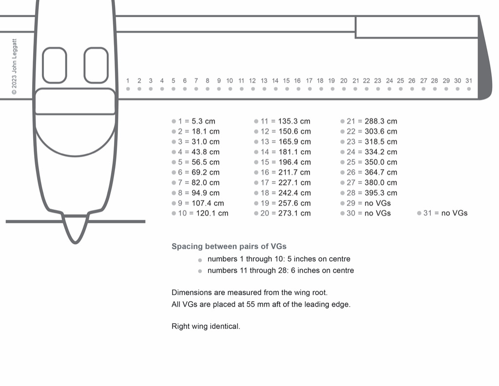
VG spacing at five-inches on centre from wing root, then six-inches on centre to wingtip
October 31, 2020
OAT: 10°, 4,500 ft AGL, max gross weight, full aft CG
| configuration | knots | |
| * power off, no flaps: | 43 | |
| * power off, half flaps: | 37 | |
| * power off, full flaps: | 36 |
| configuration | knots | |
| power on (1640 rpm) | ||
| * power on, no flaps: | 44 | |
| power on (1630 rpm) | ||
| * power on, half flaps: | 38 | |
| power on (1670 rpm) | ||
| * power on, full flaps: | 34 |
| configuration | knots | |
| top speed (2500 rpm) | ||
| * straight & level | 122 |
COMPARISON STALL-SPEEDS: NO VGs and WITH VGs INSTALLED
| configuration | no VGs | with VGs |
| * power on, no flaps: | 53 | 44 |
| * power on, half flaps: | 44 | 38 |
| * power on, full flaps: | 40 | 34 |
Vortex Generators: Horizontal Stabilizer
No audio.
Vortex Generators (VGs) installation
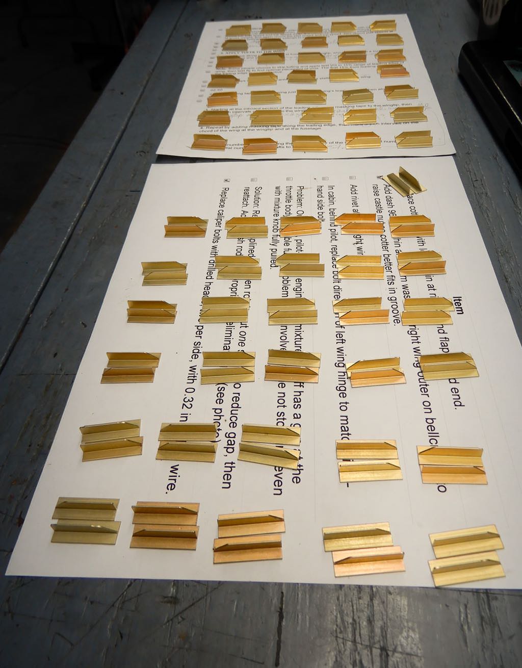
VGs after cleaning with acetone
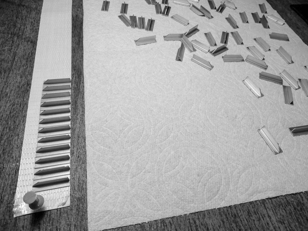
Placing VGs onto double-sided tape
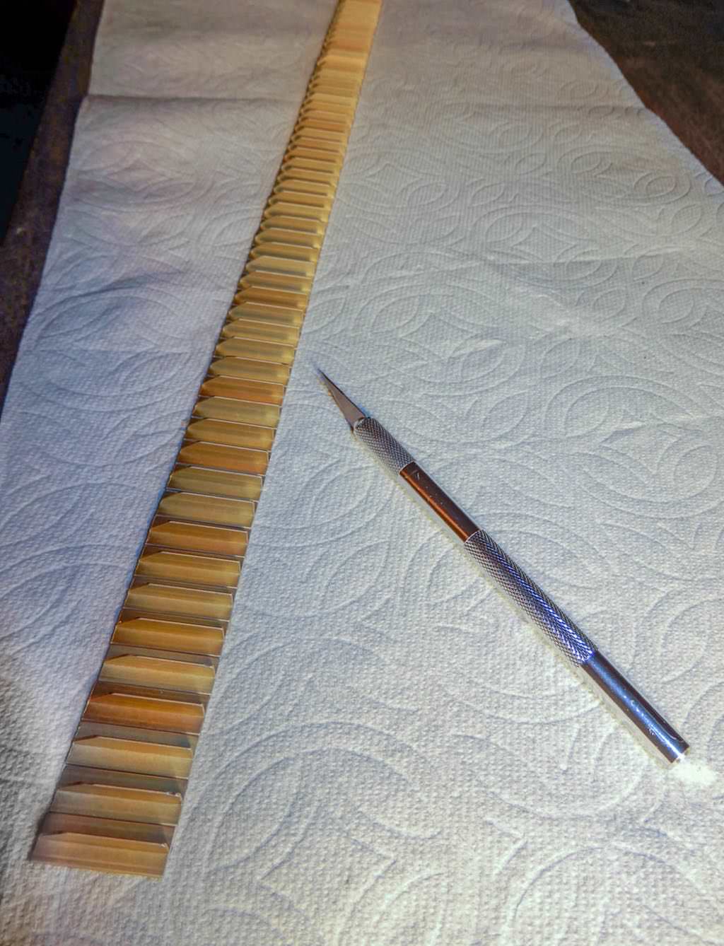
VGs joined by double-sided tape, ready for cutting into separate pieces
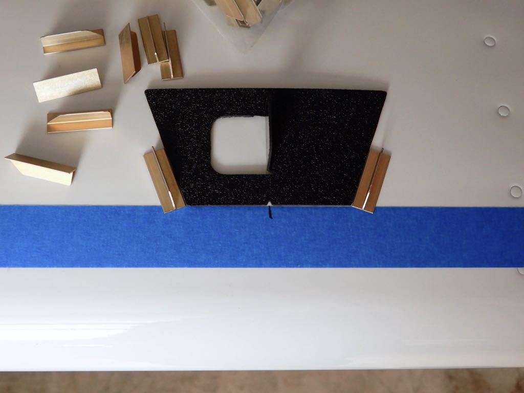
VG placement template
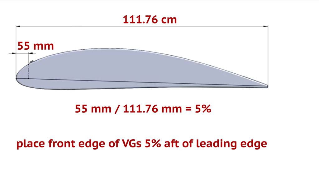
VG placement calculation
Parts List
DISCLAIMER
YOU ACKNOWLEDGE AND AGREE THIS INFORMATION IS PROVIDED ON AN "AS IS" AND "AS AVAILABLE" BASIS. YOU EXPRESSLY AGREE THAT USE OF THIS INFORMATION IS AT YOUR SOLE RISK. WE EXPRESSLY DISCLAIM ALL WARRANTIES OF ANY KIND, WHETHER EXPRESS OR IMPLIED, INCLUDING, BUT NOT LIMITED TO, THE IMPLIED WARRANTIES OF MERCHANTABILITY, FITNESS FOR A PARTICULAR PURPOSE, AND NON-INFRINGEMENT. WE MAKE NO WARRANTY AS TO THE QUALITY OF INFORMATION PROVIDED HEREIN.
For more see Privacy Statement.